The issues of dV/dt and reflective wave phenomena can be somewhat tricky concepts to understand if you haven’t been educated on them before.
If you’ve ever made waves in a pool, you’ll notice how those waves rebound off the walls of the pool and head back the way they came.
If more waves followed, the wave returning to you will inevitably collide with an oncoming wave heading in the opposite direction. When this happens, the resultant waveform climbs higher as the two forces smash into each other, causing a “spike” of sorts.
What you’ve just seen happen is what can happen in the transference of voltage in an electrical system. Colliding waves in a swimming pool isn’t a massive problem, but if those spikes were the voltage in a power system, it’s a different story. These spikes can cause damage to electrical components or even destroy an electric motor.
In the electrical industry, dealing with high-speed switching and complex signal transmission is commonplace. However, these can introduce challenges such as dV/dt and reflected wave phenomena, which can affect the performance and reliability of electrical systems. Understanding these issues and implementing effective solutions is crucial for maintaining optimal operations.
What exactly is dV/dt?
When understanding dV/dt, it can be slightly confusing figuring out what the term is in reference to. Not only does it spell out the mathematical reasoning for the issue, but it also is the term often used to describe what it causes.
The equation dV/dt represents the rate of voltage change over time, and it’s a critical parameter in electrical engineering. The “d” on each side of the equation is delta (Δ), which indicates the change, while “V” indicates voltage and “t” indicates time. It’s the rate at which the voltage in a cable changes over the time period from a transistor to a motor.
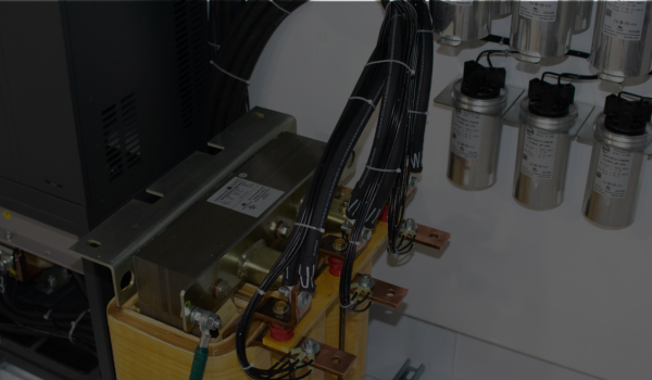
The effects of dV/dt are most often seen in the cables between variable frequency drives (VFDs) and motors. This is because VFDs usually employ the use of insulate gate bipolar transistors (IGBTs) on the output to create the simulated sine wave needed to control the speed of the motor.
This process of synthesizing electrical waveforms is called pulse width modulation (PWM). Because of the IGBTs switching on and off to generate the pulses, the waveforms generated appear more like square waves than the smooth arc of a sine wave. Closer up, those waves will show an initial sharp peak of the wave.
IGBTs are a good thing for energy efficiency and VFD performance, but it does mean that dV/dt becomes an issue. The dV/dt equation explains how the spikes in voltage can distort and even amplify over the length of the cables. The longer your cables are from your VFD to your motor, the more likely dV/dt will be a problem.
What is reflected wave phenomena?
Another part of the dV/dt issue is reflected (or reflective) wave phenomena. Similar to the whiplash effect you would see in making pulse waves on a rope or a cord, when a traveling sine wave runs into the transmission on the load side, it often meets a higher impedance level. This creates a counter-reflective waveform 180 degrees out of phase with your VFD which then travels back the other way.
The impact of that reflected wave with the waves coming from the VFD create a voltage spike that heightens the rise time of the dV/dt waveform generated by the switching of the IGBTs. As with dV/dt, reflected wave issues are exacerbated by longer cables running from the VFD to the load.
Studies have shown parallels between the switching speed of IGBTs and the presence of reflective waves in longer cables. A 2014 study reported that the maximum cable length for a given per unit overshoot decreases with increasing switching speed.
Why is dV/dt or reflective wave phenomena a problem?
The issues of dV/dt or reflective wave phenomena can sometime get overlooked due to the lack of concern from utilities. Utility providers won’t be worried about these issues because all the effects on your system are confined to the load side. In other words, as far as the utility is concerned, it’s your problem.
So why should it matter to you? The main reason is that the voltage spikes caused by dV/dt and reflected waves can seriously damage your motor’s windings. This causes several major costs, including the cost of repair, replacement, installation, and downtime. You can save both cost and headache by finding mitigation methods for dV/dt rather than just eating the cost of yet another failed motor.
The way your motor’s windings suffer from reflected waves is from an effect referred to as corona inception voltage (CIV). Voltage spikes in your cable lines can ionize the air gap between motor windings, or wherever else air is in the transmission, causing a partial discharge called corona.
CIV marks the point at which the corona effect begins causing arcing across the motor’s windings. When this point is reached, the windings can sustain damage or fail entirely. When CIV is reached in the cables, they can short-circuit and be permanently damaged as well.

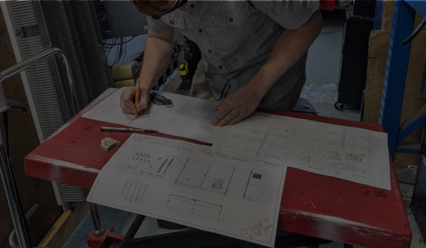
How do I fix dV/dt and reflective wave phenomena?
Before understanding different mitigation methods, it’s important to consider just how prevalent of an issue dV/dt or reflective phenomena are in your operation. Lead length is a large factor in determining the need for mitigation, and manufacturer recommendations will vary on the subject.
At Power Quality Components, we typically recommend that in low voltage drive applications, dV/dt will likely be a factor to consider for lead lengths of 100 feet or more on standard VFDs. If your lead length is 500 feet or more, the risk of dV/dt is high enough that we recommend an output filter for every standard drive.
Where reflective waves are specifically concerned, it’s important foremost to consider ways in which you can shorten the lead length between the VFD and the motor. The shorter the lead, the less likely voltage waves will get reflected.
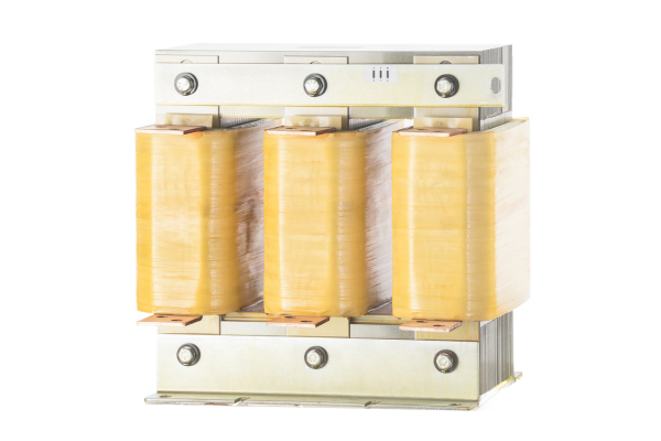
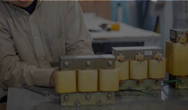
Output Reactors
An output reactor, also known as a load reactor, is the primary method that many use to reduce reflected waves. An output reactor should be installed as close to the VFD as possible in your application to have the best efficiency.
Output reactors have high capacitance and low inductance. We recommend that you should use a reactor with 5% impedance to mitigate reflected waves. The goal is to slow the rise time of the waveform while keeping peaks low, typically below 1000V on a 480V system. We’ve seen that a 5% reactor provides protection up to 1,000 feet (about 304.8 m) in most situations.
Are dV/dt filters a good idea?
A dV/dt filter seems at face value like a straightforward solution for dV/dt and reflective wave mitigation. However, further examination is important in considering if this kind of filter is truly what you need.

This graph shows the control of voltage spikes demonstrated by a 5% impedance output reactor. Graph obtained from LinkedIn.
First, consider your lead length. For most applications, the real tipping point between a basic solution and a more in-depth one is when your lead length is around 500-1,000 feet. dV/dt filters from the lead manufacturers are rated for a maximum of 1,000 feet.
A 5% output reactor is rated for the same distance, provides similar protection, and is typically both less expensive and more readily available. From our experience, dV/dt filters are typically trying to fill a performance gap between reactors and sine wave filters that doesn’t actually exist.
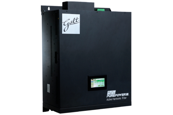
Sine Wave Filter
Sine wave filters are a much more comprehensive way of resolving dV/dt issues, particularly if your lead length is well over 1,000 feet. A sine wave filter takes the PWM waveform generated by your VFD and essentially converts it back to the sine wave from the original source.
Sine wave filters can be pricey, but they are effective up to multiple thousands of feet. For these reasons, we recommend them on lead lengths over 1,000 feet or when the cost is justified. This could be on a critical motor where downtime has a major impact. It could also be on a submersible or down-well motor where the cost to pull and replace motors is higher.
How does PQC help resolve issues with dV/dt and reflective wave phenomena?
Still unsure what type of solution is best for your system? That’s what we’re here for. PQC combines expert knowledge with top-tier components to provide robust solutions for mitigation and control.
Our team operates throughout the United States, as well as with experience in international power systems. The team consists of engineers, experts, technicians, and leaders in the power quality industry who have been addressing power issues like harmonics, power factor, and dV/dt for decades.
To work with a member of our team for solutions with your power system, contact us at 800-595-5314 or sales@pqcomponents.com.